I. Introduction: Optical Component Machining
In the field of precision optical manufacturing, the machining quality of optical components directly determines the final performance of the optical system. For components made of soft optical materials (such as calcium fluoride, zinc sulfide, zinc selenide, or certain infrared optical crystals), the machining process faces two major challenges: First, the materials are relatively soft, making them prone to surface scratches, deformation, or edge chipping during machining; second, the surface accuracy requirements are extremely high, typically requiring sub-micron or even nanometer-level surface shape errors. These two challenges overlap, making the traditional “grind first, then core” process route difficult to guarantee final quality.
As a professional optical component manufacturer, MOK Optics has established a core process principle of “core first, then grinding” to address the challenges of soft materials and high surface accuracy requirements. “Core first, then grinding” means that before precision grinding and polishing, the core-taking process (i.e., fine-tuning the outer diameter and end face) is completed first to ensure the accurate establishment of the lens’s geometric positioning reference before subsequent surface finishing. The core logic behind this sequential arrangement is that if grinding is performed before core extraction on soft materials, the already machined high-precision surface shape is easily damaged by clamping and core extraction stress. “Core extraction first, then grinding” ensures that surface shape processing is always based on a stable and precise benchmark, thus effectively guaranteeing the final yield.
The following will describe MOK Optics’ process specifications and control points for each stage of the optical component manufacturing process, from blank to finished product, in stages including roughing, sanding, core extraction, grinding, and inspection.

II. Material Selection and Pre-treatment: The Starting Point of the Process
2.1 Blank Selection and Initial Inspection
The processing of optical components begins with the selection of raw materials. MOK Optics purchases blanks of the corresponding grades from verified optical material suppliers according to customer order requirements. For soft materials, a preliminary inspection is required upon blank receipt, including: material grade confirmation, bubble and streaking detection, initial thickness and diameter measurement, and visual inspection for obvious cracks or inclusions on the surface. Only blanks that pass the inspection can proceed to subsequent processing stages.
2.2 Rough Grinding – Establishing the Basic Shape and Thickness
Rough grinding is the first machining step, its purpose being to quickly machine the blank to a basic shape close to the final dimensions and establish a thickness reference. MOK Optics uses high-rigidity CNC milling equipment with diamond grinding wheels for rough grinding of the blank. The rough grinding stage requires removing casting or cutting allowances from the blank surface, typically between 0.5 mm and 2.0 mm per side, depending on the initial blank dimensions and finished product specifications.
Due to the relatively soft material, the coolant flow rate, grinding wheel speed, and feed rate need to be strictly controlled during rough grinding. Insufficient coolant can lead to excessive localized temperature rise, causing thermal deformation or even surface burns; excessive feed rate may cause edge chipping or excessive surface roughness. The rough-ground lens will proceed to the next process, with noticeable grinding wheel marks remaining on its surface, which is normal and will be removed in the subsequent sanding process.
III. Sanding: A Transition from Roughing to Finishing
3.1 The Role of Sanding
Sanding (also known as fine grinding or finishing) plays a crucial role between roughing and core taking. Its main tasks are twofold: first, to remove tool marks and surface damage left from the roughing stage; second, to provide a uniform machining allowance and consistent surface finish for subsequent grinding processes. Poor sanding results in residual tool marks or an uneven surface layer, directly leading to uncontrolled surface profiles or localized edge collapse during the grinding stage.
3.2 Sanding Equipment and Abrasive Selection
MOK Optics uses a double-sided fine grinding machine for sanding, selecting silicon carbide or alumina abrasives of different grit sizes based on the lens material and specifications. Sanding typically involves two or even three sub-processes: coarse sanding uses coarser abrasive (e.g., #600–#1000) to quickly remove rough edges and tool marks; fine sanding uses even finer abrasive (e.g., #1500–#3000) to further reduce surface roughness and refine the surface shape.
For soft materials, sanding pressure needs precise control. Excessive pressure can cause lens deformation or edge collapse, while insufficient pressure results in low grinding efficiency. MOK Optics’ process parameter database sets recommended pressure ranges, grinding wheel speeds, and processing times for different material grades (e.g., H-K9L, fused silica, calcium fluoride, etc.). Operators retrieve the corresponding parameters according to the work order.
3.3 Transmittance Inspection—A Key Quality Control Point After Sanding
After sanding, MOK Optics mandates an important intermediate inspection—transmittance inspection. The inspection method is as follows: The sanded lens is placed in a standard light source box, typically using a D65 standard illuminator. An observer looks through the lens at the standard lettering or grid board below. The acceptance criteria include three dimensions:
Letter Clarity: The edges of the lettering observed through the lens should be sharp, without significant blurring or ghosting. Blurred lettering usually indicates residual tool marks or abnormal local curvature of the surface.
No Shadows: There should be no localized dark areas or shadows within the lens’s light-transmitting area. Shadows often originate from uneven stress distribution within the material or subsurface damage caused during the sanding process.
Uniformity: The uniformity of light transmission across the entire lens surface must meet the acceptance requirements; that is, the brightness variation from the center to the edge should be imperceptible to the human eye.
Only lenses that simultaneously meet all three criteria can proceed to the core-taking process. For lenses that fail the light transmission inspection, MOK Optics will decide whether to rework or scrap them, depending on the circumstances, to prevent defective products from entering subsequent high-value processes.
IV. Core Grinding: Refining Outer Diameter and End Face, Establishing a Precision Datum
4.1 Significance of Core Grinding
Core grinding (also known as centering edge grinding) is the core process in the “core first, then grinding” principle. Its task is to refine the outer diameter and end face of the lens, while simultaneously machining chamfers, ultimately aligning the geometric axis of the lens with the optical axis (i.e., “centering”). For soft material optical components, the outer diameter and end face of the lens after core grinding become the unified datum for subsequent grinding, coating, and assembly. The accuracy of the datum directly determines the consistency of the final optical system assembly.
4.2 Core Grinding Equipment and Processing Parameters
MOK Optics uses a high-precision centering edge grinding machine for core grinding. The equipment is equipped with an optical centering system that can monitor the optical eccentricity of the lens during rotation in real time and automatically adjust the clamping position until the eccentricity meets the requirements. During processing, a diamond grinding wheel performs micro-grinding on the outer diameter and end face, simultaneously machining the chamfer.
The chamfering is completed at this stage, which is a standard process of MOK Optics. The purpose of chamfering is to eliminate sharp edges on the lens, preventing edge chipping during subsequent handling, grinding, or assembly. Chamfering also provides a smooth edge transition zone for the coating process. The geometric dimensions (width and angle) of the chamfer must strictly adhere to the drawing requirements.
4.3 Measurement of Chamfer Angle using a 2D Image Analyzer
The cored lens immediately enters the chamfer inspection stage. MOK Optics uses a 2D image analyzer (a non-contact optical measuring instrument) to measure the chamfer angle. The operating steps are as follows: Place the lens on the image analyzer’s worktable, adjust the light source to obtain a clear edge contour image, and capture the angle between the chamfer bevel and the end face or outer diameter using the measurement software. The measurement result is directly compared with the nominal value on the drawing. The typical chamfer angle tolerance is ±5° or tighter, depending on customer requirements.
If the measurement value meets the standard, the lens proceeds to the next process; if it fails, the chamfer is re-trimmed on a centering edge grinding machine, or it is disposed of as a defective product, depending on the circumstances. It is important to emphasize that the cost of defective lenses generated during the core extraction process is high because the lens has already undergone two processing steps: roughing and sanding. Therefore, MOK Optics conducts a second inspection of sanded lenses before core extraction to minimize the risk of core extraction failure due to abnormalities in the previous process.
V. Grinding: The Core Step in Surface Finishing
5.1 Clamping and Fixture Preparation
Lens that pass core extraction are loaded into a dedicated grinding fixture. For soft materials, the clamping method is particularly critical. MOK Optics uses vacuum suction or low-stress elastic chucks for clamping, avoiding lens deformation or surface indentations caused by rigid clamping. The fixture’s positioning reference surface precisely matches the lens’s outer diameter and end face, ensuring stable and repeatable lens posture on the grinding machine.
Before clamping, the operator must clean the contact surfaces between the fixture and the lens using a lint-free cloth and anhydrous ethanol to remove any particles that could cause clamping errors. This step, though small, is a crucial detail for ensuring the repeatability of the ground surface.
5.2 Grinding Machines and Process Parameters
MOK Optics is equipped with multiple high-precision single-axis or bi-axis grinding machines, allowing selection of appropriate equipment based on lens type (spherical, aspherical, or planar). The grinding slurry uses cerium oxide, aluminum oxide, or diamond micron powder suspensions, with particle sizes gradually transitioning from a few micrometers to submicrometers. Grinding is typically divided into two stages: roughing and finishing.
Roughing: Using a larger particle size grinding slurry (e.g., 3–5 μm), the damaged layer remaining from abrasive deposits is quickly removed, and the surface profile is initially formed. The surface profile error after roughing is typically controlled within 0.5–1 aperture stop.
Finishing: Using a finer grinding slurry (e.g., 0.5–1 μm), the surface roughness is further reduced, and the surface profile error is corrected to the final requirements. After finishing, the surface profile error can reach 0.2 aperture stops or even higher, and the surface roughness Ra can reach the nanometer level.
For soft materials, the grinding pressure should be gradually reduced from coarse to fine grinding. Simultaneously, the rotation speed and oscillation amplitude of the grinding disc must be adjusted accordingly to prevent surface distortion caused by frictional heat or mechanical stress.
5.3 Intermediate Inspection After Grinding
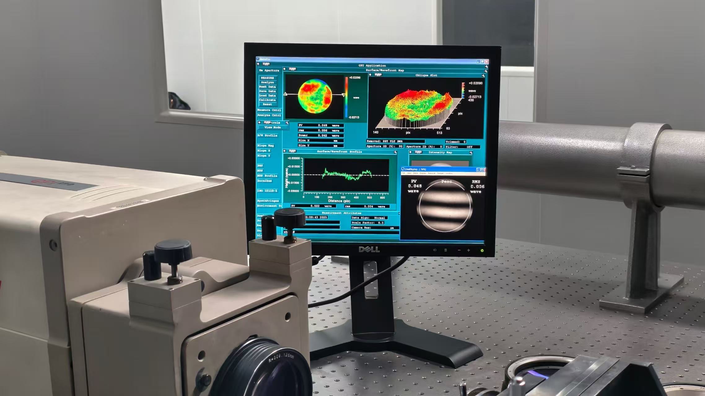
After fine grinding, MOK Optics will conduct a preliminary inspection of the surface shape, typically using a laser interferometer to measure surface shape errors. If the surface shape meets the standards, the lens enters the final appearance inspection stage; if it does not meet the standards, rework or re-grinding with adjusted grinding parameters will be determined based on the deviation.
VI. Appearance Inspection: Confirmation of Consistency with Customer Requirements
6.1 Appearance Inspection Under Standard Light Source
After grinding, the optical components require a final appearance inspection. MOK Optics conducts the inspection under standard light source conditions according to the generally accepted inspection standards in the optical industry. The inspection environment requirements are as follows: a dark or semi-dark room environment, a D65 standard illuminator (color temperature 6504 K), an illuminance between 800 and 1200 lux, and a black non-reflective velvet background. Inspectors must undergo standard vision testing and defect identification training before being allowed to operate the equipment.
Appearance inspection items include, but are not limited to:
Scratches and pitting: According to GB/T 1185 or ISO 10110-7 standards, the width and length of scratches and the diameter and number of pits on the lens surface are judged.
Bubbles and impurities: For soft materials, internal bubbles and impurities are clearly visible under transmitted light; acceptance must be compared with the customer’s allowed specifications.
Chipping: Edge chipping is measured using a 20x or 40x microscope to determine if it exceeds the standard.
Surface contamination: Check for fingerprints, oil stains, water stains, or residual grinding powder.
6.2 Comparison of Inspection Values and Acceptance Judgment
The core of appearance inspection is to compare each inspected value with the customer’s requirements (drawings or technical agreements) item by item. MOK Optics has established a digital inspection record system for this purpose. Inspectors directly enter measurement data via tablet computer, and the system automatically judges whether each item is within the tolerance range. Lenses are considered合格 (qualified/acceptable) only when all appearance, surface shape, and dimensional indicators meet customer requirements.
For non-conforming products, MOK Optics implements a clear classification and handling process: reworkable products (such as those with minor scratches that can be removed by repolishing) are returned to the appropriate process for rework; non-reworkable products (such as those with severe chipping or internal material cracks) are scrapped, and the reasons for non-conformity are recorded for process improvement.
VII. Summary: MOK Optics’ Process Control Advantages
Reviewing the complete optical component processing flow—from material selection, roughing, sanding, light transmission inspection, core taking, chamfering measurement, grinding to final appearance inspection—each step reflects MOK Optics’ targeted approach to the challenges of processing soft materials. The core principle of “core first, then grinding” is consistently applied, ensuring the stability of the baseline and controllable stress of soft materials during processing. Light transmission inspection, as a crucial checkpoint after sanding, effectively prevents substandard semi-finished products from entering the high-value core taking and grinding processes. The precise measurement of the chamfer angle by the 2D imaging system demonstrates MOK Optics’ rigorous control over dimensional details. Finally, the visual inspection under standard lighting conditions and the item-by-item comparison with customer requirements are the ultimate fulfillment of the quality commitment.